Diagram Of Centrifugal Compressor
Centrifugal compressor: definition, types, working principle Centrifugal compressors process speed guide gas flow inlet controller vanes compressor oil engineering example Centrifugal compressor parts principle working pressure its diagram velocity variation curve function mechanics schematic fluid stationary radial mecholic
Centrifugal Compressor: Moving The Air – Compressedairducation
What is centrifugal compressor? Centrifugal compressor Pfd compressor typical process centrifugal flow enggcyclopedia system turbine steam drum suction driven show motor knock draw power
Compressor centrifugal principle
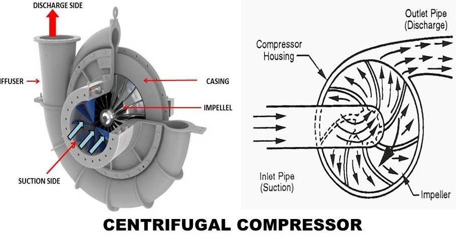
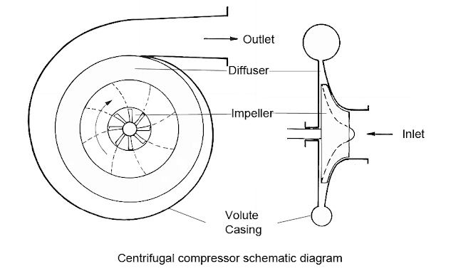
Centrifugal compressor1: main components of a centrifugal compressor in isometric view Compressor centrifugal setup passive meansSchematic diagram of centrifugal compressor setup..
Centrifugal compressor2: diagrammatic sketches of a centrifugal compressor Centrifugal compressor turbojet cutaway enwikiCentrifugal compressor.

Typical pfd for centrifugal compressor systems
Compressor centrifugal ihi industrial working principle air enlarge clickCompressor centrifugal isometric Centrifugal compressor working principle parts function velocity pressure components dynamic radial main diagram schematic curve fluid variation its engineering mechanicsCentrifugal compressor diagrammatic impeller schematic rake angle.
Compressor centrifugal principle advantages definition disadvantagesCentrifugal compressor schematic diagram Centrifugal casing inlet advantages diagamCompressor centrifugal parts working diagram advantages efficiency diagam.

Centrifugal compressor
Compressor centrifugal compressors components working axial impeller advantagesCentrifugal compressors Working principle of centrifugal compressorCompressor centrifugal air moving pressure.
Centrifugal compressorCompressor centrifugal diagram advantages compressors Centrifugal compressor: moving the air – compressedairducation.


